Iranian Classification Society Rules

< Previous | Contents | Next >
Section 9 Crankcase Explosion Relief valves
901. Application
The requirements in this Section apply to tests and inspections for the type approval of crankcase explosion relief valves intended to be fitted to engines and gear cases in accordance with the re- quirements of Pt 5, Ch 2, 203. 5. of the Rules. This test procedure is only applicable to ex- plosion relief valves fitted with flame arresters.
902. Data to be submitted
The following reference data are to be submitted to the Society in addition to those specified in
102.
(1) Accreditation certificate of test house
(2) Details of test vessel and attachment
(3) Test data performed previously at the manufacturer's works
903. Type tests
1. Test houses
The test houses where testing is carried out are to be accredited to a National or International Standard, e.g. KS A ISO IEC 17025, and the test facilities are to be equipped so that they can perform and record explosion testing in accordance with The requirements in this Section
2. Valves to be tested
(1) The valves used for type test shall be selected from the manufacturer’s normal production line by the Surveyor witnessing the tests and three valves for each size shall be selected. However, in case where the valves produced in series comply with the requirements specified in 4., type test may be exempted.
(2) The valves selected for type testing are to have been previously tested at the manufacturer's works to demonstrate that the opening pressure is in accordance with the specification within a
tolerance of ±20% and that the valve is air tight at a pressure below the opening pressure at least 30 seconds.
for
(3) In case where the orientation of installation could be changed, the valves are
each intended installation orientation.
3. Approval tests are to comply with the requirements given in Table 3.9.1.
to be tested for
Table 3.9.1 Type test and acceptance criteria of Crankcase Explosion Relief valve
Kinds | Requirements |
Explosion test process | (1) All explosion tests to verify the functionality of crankcase explosion relief valves are to be carried out us- ing an air and methane mixture with a methane concentration of 9.5 % ±0.5 %. The pressure in the test vessel is to be not less than atmospheric and not exceed 0.2 bar. (2) The concentration of methane in the test vessel is to be measured in the top and bottom of the vessel and is not to differ by more than 0.5%. (3) The ignition of the methane and air mixture is to be made at the centreline of the test vessel at a position approximately one third of the height or length of the test vessel opposite to where the valve is mounted. (4) The ignition is to be made using a maximum 100 joule explosive charge. |
Test vessel for explosion testing | (1) The test vessel for explosion testing is to have documented dimensions. The dimensions are to be such that the vessel is not "pipe like" with the distance between dished ends being not more than 2.5 times its diameter. The internal volume of the test vessel is to include any standpipe arrangements. (2) The pressure measuring equipment is to be capable of measuring the pressure in the test vessel in at least two positions, one at the valve(P2 in Fig 3.9.1) and the other at the test vessel centre(P1 in Fig 3.9.1). The measuring arrangements are to be capable of measuring and recording the pressure changes throughout an explosion test at a frequency recognising the speed of events during an explosion. The result of each test is to be documented by video recording and if necessary by recording with a heat sensitive camera. (3) The test vessel is to be provided with a flange, located centrally at one end perpendicular to the vessel longitudinal axis, for mounting the explosion relief valve. The test vessel is to be arranged in an ori- entation consistent with how the valve will be installed in service, i.e., in the vertical plane or the hori- zontal plane. |
86 Guidance for Approval of Manufacturing Process and Type Approval, Etc. 2015
![]()
![]()
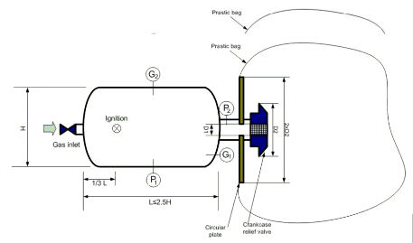
Table 3.9.1 Type test and acceptance criteria of Crankcase Explosion Relief valve
Kinds | Requirements | |
Test vessel for explosion testing | (4) A circular plate is to be provided for fitting between the pressure vessel flange and valve to be tested with the following dimensions: a) Outside diameter of 2 times the outer diameter(D2 in Fig 3.9.1) of the valve top cover. b) Internal bore having the same internal diameter(D1 in Fig 3.9.1) as the valve to be tested. (5) The test vessel is to have connections for measuring the methane in air mixture at the top(G2 in Fig 3.9.1) and bottom(G1 in Fig 3.9.1). (6) The test vessel is to be provided with a means of fitting an ignition source at a position approximately one third of the height or length of the test vessel opposite to where the valve is mounted. (7) The test vessel volume is to be as far as practicable, related to the size and capability of the relief valve to be tested. In general, the volume is to correspond to the requirement for the free area of explosion relief valve to be not less than 115 cm m of crankcase gross volume. This means that the testing of a valve having 1150 cm of free area, would require a test vessel with a volume of 10 m . Where the free area of relief valves is greater than 115 cm m of the crankcase gross volume, the volume of the test vessel is to be con- sistent with the design ratio. In no case is the volume of the test vessel to vary by more than +15% to -15% from the design cm m volume ratio. (8) The test facilities are to have equipment for controlling and measuring a methane gas in air concentration within a test vessel to an accuracy of ± 0.1%. | |
Explosion testing | General | (1) Where valves are to be installed on an engine or gear case with shielding arrangements to deflect the emission of explosion combustion products, the valves are to be tested with the shielding arrangements fitted. (2) Successive explosion testing to establish a valve's functionality is to be carried out as quick- ly as possible during stable weather conditions. (3) The pressure rise and decay during all explosion testing is to be recorded. (4) The external condition of the valves is to be monitored during each test for indication of any flame release by video and heat sensitive camera. (5) For obtaining the type approval, the explosion testing for each valves shall be done for three stages respectively. |
Stage 1 | Two explosion tests are to be carried out with the flange opening fitted with the circular plate covered by a 0.05 mm thick polythene film. These tests establish a reference pressure level for determination of the effects of a relief valve in terms of pressure rise in the test vessel. | |
Stage 2 | (1) Two explosion tests are to be carried out on three different valves of the same size. Each valve is to be mounted in the orientation that it requires approval for installation i.e., in the vertical or horizontal position with the circular plate located between the valve and pressure vessel mounting flange. | |
Guidance for Approval of Manufacturing Process and Type Approval, Etc. 2015 87
![]()
![]()
Table 3.9.1 Type test and acceptance criteria of Crankcase Explosion Relief valve (continued)
Kinds | Requirements | |
Explosio n testing | Stage 2 | (2) The first of the two tests on each valve is to be carried out with a 0.05mm thick poly- thene bag, having a minimum diameter of three times the diameter of the circular plate and volume not less than 30% of the test vessel, enclosing the valve and circular plate. Before carrying out the explosion test the polythene bag is to be empty of air. The poly- thene bag is required to provide a readily visible means of assessing whether there is flame transmission through the relief valve following an explosion. (During the test, the explosion pressure will open the valve and some unburned methane/air mixture will be collected in the polythene bag. When the flame reaches the flame arrester and if there is flame transmission through the flame arrester, the methane/air mixture in the bag will be ignited and this will be visible.) (3) Provided that the first explosion test successfully demonstrated that there was no indication of combustion outside the flame arrester and there are no visible signs of damage to the flame arrester or valve, a second explosion test without the polythene bag arrangement is to be carried out as quickly as possible after the first test. During the second explosion test, the valve is to be visually monitored for any indication of combustion outside the flame arrester and video records are to be kept for subsequent analysis. The second test is required to demonstrate that the valve can still function in the event of a secondary crankcase explosion. (4) After each explosion, the test vessel is to be maintained in the closed condition for at least 10 seconds to enable the tightness of the valve to be ascertained. The tightness of the valve can be verified during the test from the pressure/time records or by a separate test after completing the second explosion test. |
Stage 3 | Carry out two further explosion tests as described in Stage 1. These further tests are required to provide an average base line value for assessment of pressure rise recognising that the test vessel ambient conditions may have changed during the testing of the explosion relief valves in Stage 2. | |
Assessment and records | (1) The valves to be tested are to have evidence of design appraisal/approval by the Society (2) The designation, dimensions and characteristics of the valves to be tested are to be recorded. This is to include the free area of the valve and of the flame arrester and the amount of valve lift at 0.2bar. (3) The test vessel volume is to be determined and recorded. (4) For acceptance of the functioning of the flame arrester there is not to be any indication of flame or combustion outside the valve during an explosion test. This should be con- firmed by the test laboratory taking into account measurements from the heat sensitive camera. (5) The pressure rise and decay during an explosion is to be recorded, with indication of the pressure variation showing the maximum overpressure and steady underpressure in the test vessel during testing. The pressure variation is to be recorded at two points in the pres- sure vessel. (6) The effect of an explosion relief valve in terms of pressure rise following an explosion is ascertained from maximum pressures recorded at the centre of the test vessel during the three stages. The pressure rise within the test vessel due to the installation of a relief valve is the difference between average pressure of the four explosions from Stages 1 and 3 and the average of the first tests on the three valves in Stage 2. The pressure rise is not to exceed the limit specified by the manufacturer. (7) The valve tightness is to be ascertained by verifying from the records at the time of test- ing that an underpressure of at least 0.3bar is held by the test vessel for at least 10 sec- onds following an explosion. This test is to verify that the valve has effectively closed and is reasonably gas-tight following dynamic operation during an explosion. (8) After each explosion test in Stage 2, the external condition of the flame arrester is to be examined for signs of serious damage and/or deformation that may affect the operation of the valve. (9) After completing the explosion tests, the valves are to be dismantled and the condition of all components ascertained and documented. In particular, any indication of valve sticking or uneven opening that may affect operation of the valve is to be noted. Photographic re- cords of the valve condition are to be taken and included in the report. | |
88 Guidance for Approval of Manufacturing Process and Type Approval, Etc. 2015
![]()
![]()
4. Design series qualification
(1) The qualification of quenching devices to prevent the passage of flame can be evaluated for other similar devices of identical type where one device has been tested and found satisfactory.
(2) The quenching ability of a flame arrester depends on the total mass of quenching lamellas/mesh.
Provided the materials, thickness of materials, depth of lamellas/thickness of mesh layer and the quenching gaps are the same, then the same quenching ability can be qualified for different sizes of flame arresters subject to (a) and (b) being satisfied. However valves which could not be subjected to this method shall be verified by the method as deemed appropriate by the Society.
(a)
(b)
Where:
total depth of flame arrester corresponding to the number of lamellas of size 1 quenching
= device for a valve with a relief area equal to
total depth of flame arrester corresponding to the number of lamellas of size 2 quenching
device for a valve with a relief area equal to
= free area of quenching device for a valve with a relief area equal to
= free area of quenching device for a valve with a relief area equal to
(3) The qualification of explosion relief valves of larger sizes than that which has been previously satisfactorily tested in accordance with this Section can be evaluated where valves are of identi- cal type and have identical features of construction subject to the following:
(a) The free area of a larger valve does not exceed three times + 5% that of the valve that has been satisfactorily tested.
(b) One valve of the largest size, subject to (a), requiring qualification is subject to satisfactory
testing required by 903. 2. (2) and stage 2 explosion testing specified in Table 3.9.1 except that a single valve will be accepted in item (1) of stage 2 explosion testing and the volume of the test vessel is not to be less than one third of the volume required in item (7) of test vessel specified in Table 3.9.1
(c) The assessment and records are to be in accordance with the requirements specified in Table
3.9.1 noting that item (6) will only be applicable to Stage 2 for a single valve.
(4) The qualification of explosion relief valves of smaller sizes than that which has been previously satisfactorily tested in accordance with this Sections can be evaluated where valves are of iden- tical type and have identical features of construction subject to the following:
(a) The free area of a smaller valve is not less than one third of the valve that has been sat- isfactorily tested.
(b) One valve of the smallest isfactory testing required by
size,
903.
subject to (a), requiring qualification is subject to sat-
2. (2) and stage 2 explosion testing specified in Table
3.9.1 except that a single valve will be accepted in item (1) of stage 2 explosion testing
and the volume of the test vessel is not to be more than the volume required in item (7) of test vessel specified in Table 3.9.1
(c) The assessment and records are to be in accordance with the requirements specified in Table
3.9.1 noting that item (6) will only be applicable to Stage 2 for a single valve.
(5) Valves passed the type tests specified in this Section and valves having sizes between valves qualified according to the requirements in (3) and (4) may be qualified without type tests pro-
vided that calculation result of (2) is satisfactory.
5. Test report
The test facility is to deliver a full report that includes the following information and documents:
(1) Test specification.
(2) Details of test pressure vessel and valves tested.
(3) The orientation in which the valve was tested, (vertical or horizontal position).
(4) Methane in air concentration for each test.
Guidance for Approval of Manufacturing Process and Type Approval, Etc. 2015 89
![]()
(5) Ignition source
(6) Pressure curves for each test.
(7) Video recordings of each valve test.
(8) The assessment and records stated in Table 3.9.1
90 Guidance for Approval of Manufacturing Process and Type Approval, Etc. 2015
![]()